FUEL SYSTEM
The fuel system consists of three tanks - one in each wing plus
a main tank forward of
the instrument panel, two fuel pumps: a full time engine driven pump
and an electric pump,
transfer pump, selector panel, three quantity indicators, fuel flow
gauge and interconnecting
vent system.
Fuel Tanks and Vent System
The leading edge of each outboard wing section is a sealed fuel
tank with a capacity of
18 gallons, almost all of which is usable. At the inboard rib near the lower
wing attach point is the
fuel pickup with a finger strainer. At the low point of each wing tank
is a quick drain. Inside
the tank near the filler cap is the vent / overflow tube. All tanks
and the fuel quantity
standpipes are interconnected by the vent system. The vents open to
outside air at each wingtip
and just aft of the firewall below the copilot's rudder pedals. The
main tank is between the
instrument panel and the firewall and has a capacity of 25 gallons,
all useable. The main tank
has a finger strainer at it's outlet.
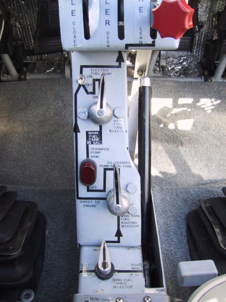
Fuel Selection
The fuel selector panel is schematically arranged to show how
the tanks, selector
valves, transfer pump and electric fuel pump are plumbed. Wing tank
fuel first flows through a
"LEFT, RIGHT, BOTH, OFF" selector and then to the "WING FUEL ROUTING"
selector. This selector
enables the pilot to route the fuel to the transfer pump to be pumped
into the main tank for
normal operation, or directly to the engine if desired.
Selection of "DIRECT TO ENGINE" may be desired in the event of
transfer pump failure, a
problem with the main tank or it's quantity indicator, or possibly
for center of gravity
purposes. The main tank has an "ON, OFF" selector valve at it's outlet.
After fuel leaves the
selector panel, it flows through a gascolator / drain at the lower
left rear of the engine
compartment, the electric fuel pump, the engine driven fuel pump and
then into the fuel
injector.
Fuel Quantity Indicating System, Transfer Pump
The fuel quantity in each tank is accurately measured with electronic
capacitance type
probes from
Sky
Sports
® (now sold by Aircraft Spruce).
The main tank's probe in addition to indicating tank quantity, has a calibrated
sensor that triggers the transfer pump relay to activate the transfer pump
(if armed) when the main
tank quantity drops to three fourths full. The transfer pump switch
light will illuminate when
the transfer pump is operating. The transfer pump and it's relay are
located under the copilot's
floorboard.
The quantity of each wing tank is measured by a probe in a vented
standpipe near each
Electrical power is supplied by a 12 volt, direct current system.
The system includes a
A dual volt / amp meter indicates system performance. The gauge
is designed so that
The split BAT / ALT Master switch "BAT" side energizes the master
solenoid to provide
The circuit breakers automatically break the electrical circuit
if an overload should
Suction for the vacuum operated gyro instruments - the attitude
indicator and the
Static air and pitot pressure are supplied by the heated pitot
head under the left wing.
pilot's outboard knee.
Fuel System Schematic
Photo of fuel panel
ELECTRICAL SYSTEM
12 volt 45 ampere alternator, regulator and 35 ampere hour battery to
produce electrical power.
The battery is located in a sealed box aft of the baggage compartment.
On the right side of the
fuselage near the battery is an external power receptacle enabling
the use of an automotive
battery or external battery charger assist for starting or charging.
The aircraft Master
Switch must be on for the external power relay to be energized to provide
power to the aircraft
battery and electrical system.
normal operation is indicated with both needles at or above level.
Charging
is indicated by a
positive ammeter reading and a voltage between 13 and 14.5 volts.
power to the main bus and lower row of circuit breakers. The "ALT"
side of the switch energizes
the alternator field turning the alternator on to enable it to recharge
the battery. The AVIONICS
MASTER switch / circuit breaker energizes the upper row of circuit
breakers providing power to
the avionics. This switch is normally off for engine start. The engine
starter solenoid is
located near the base of the copilot's control stick and is activated
by the magneto key switch.
occur. To reset the circuit breaker simply push in the reset button.
It may be necessary to
allow approximately two minutes for cooling before resetting a circuit
breaker. Corrective
action should be taken in the event of continual circuit breaker popping
or a circuit breaker
that will not stay reset. It is possible to manually trip a breaker
by pulling out on the reset
button.
The alternator is an Air-Tec (Hitachi) Model AM-0053R 45 amp.
The regulator is a V1200 voltage regulator with overvoltage protection,
also from Air-Tec Inc. Orlando, FL (800) 366-4746. Owner: Dick Waters.
Electrical System Schematic
Current schematic with alternator
Former schematic with generator
VACUUM SYSTEM
heading indicator is supplied by an engine driven vacuum pump. Air
is drawn into the central
air filter located behind the airspeed indicator, drawn through the
two instruments, through an
adjustable vacuum regulator located on the firewall forward of the
copilot's rudder pedals to
the vacuum pump. Suction is indicated on the suction gauge located
immediately beneath the
vacuum operated instruments. Normal operating range is 4.8 to 5.1 inches
of mercury.
Vacuum System Schematic
PITOT and STATIC SYSTEM
Pitot pressure is provided to the airspeed indicator and static pressure
is provided to the
airspeed indicator, vertical speed indicator and encoding altimeter.
Pitot / Static System Schematic
[ HOME PAGE ]
[ CONTACT ]
[ LESSONS LEARNED ]
[ FREQUENT QUESTIONS ]