Additional Modifications
Mustang II Experimental Airplane N727RH

Updated October 30, 2018
(first published: July 16, 2004)
Click on small image or underlined text for a larger image.
After viewing larger image select "Back" on your browser.

These photos incorporate deviations from the plans.
Use of this information for Your aircraft is obviously AT YOUR OWN RISK.


To slew ahead, click on the sections below:
Cruise and Airspeed Calibration
Slow Flight and Airspeed Calibration
Tailwheel Mod (Updated 10/30/2018)

Modifications in progress

This page will be a 'work in progress' to share what I'm doing with modifications.

July 3, 2004

I started an attempt to reduce cooling drag by reducing the original Twin Comanche cowl inlets by 33%. Original openings totaled 55 in², now at 36 in². They are filled with balsa, foam and tape for trial purposes.
My goal with these modifications is to maximize the 75% power cruise at 2400 RPM (near 8,000' DA) - currently at 166 KTAS, while still being able to climb and cruise at 17,000' when tailwinds favor that.


Reduced cowl openings
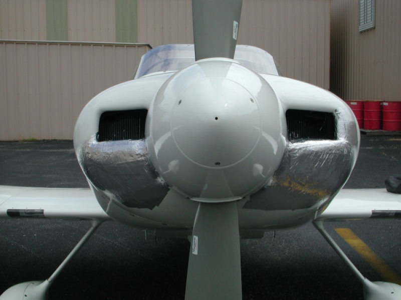
Reduced cowl
openings

Previously 55in²,
now 36 in²
(107 KB)
Top of climb at 17,000'
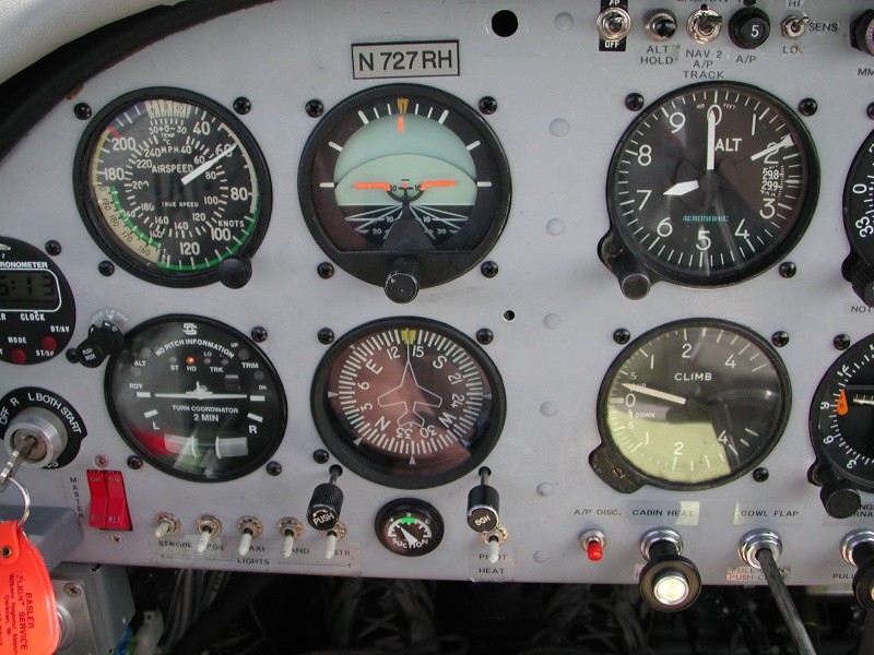
Top of climb
at 17,000'

GW=1509#
Climb power =
full throttle (15.0")
2500 RPM
(138 KB)
Cruise at 17,000'
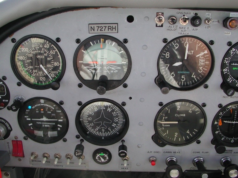
Cruise at 17,000'

IAS 107 K, TAS 144 K
FF= 6.2 GPH, OAT= -2.7°C
DA=18,900'
(136 KB)
Cruise at 7,000'
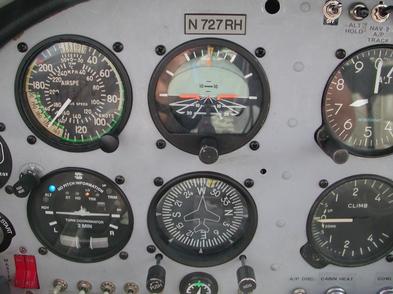
Cruise at 7,000'

IAS 145 K, TAS 166 K
FF= 8.8 GPH, OAT= +17.6°C
2400 RPM, DA=8,900'
(Above optimum Density Altitude)
(133 KB)
The primary purpose was to collect CHT and oil temperature data to confirm that the reduced inlets would not over-temp the engine. They were normal even though the atmosphere was ISA +13° at sea level (28°C).
Cruise data was collected at 17,000'; 15,000'; 13,000'; 11,000', 7,000' and 6,000'.
I erred by reducing the throttle at 6,000' to set MP for 75% cruise for a standard day: 23.1" MP, when I should have corrected for the non-standard temperature by running at 23.6" MP - just about full throttle - which would have been very close to the optimum density altitude for a 75% power setting at 2400 RPM.
I estimate that approximately one more knot would have been achieved if I'd collected 75% data at the optimum altitude.
New data will be collected when the fiberglass work is complete, which should smooth the flow into the engine somewhat.
Plans are to also reduce the cowl flap outlet area and later, add exhaust nozzles.

Later Update Note: I was experiencing carbon monoxide leaking into the cabin and have been able to significantly reduce it with down-turned 'piccolo' exhaust extensions.
Wick's photo here
They are not very attractive and have affected my cruise speed, but reducing the CO was a higher priority for me.


December 5, 2009

Cruise flight test and airspeed calibration

The intent was to determine what my "normal best cruise speed" is at optimum altitude at 75% power, full throttle and see if GPS verified speeds agreed with the IAS and calculated TAS.
Test was flown at 8,500', OAT -3° C, QNH 30.21", 1785 lbs., CG 72.5", full throttle, 21.8" MP, 2400 RPM, mixture at 75° ROP / 8.6 GPH.
I calculated the DA to be 8050', which is very close to what the PA-30 manual shows to be the DA with best TAS at 75% power. Considering the power setting chart for the engine, I believe the engine was producing 72.5% power under these conditions. If I had to do over, I would re-run the same test 1,000' lower and I believe that would have generated the desired 75%.
IAS was 139 K, yielding a [calculated] TAS of 159 K
Groundspeeds on the four cardinal headings: 360°=151 K, 090°=184 K, 180°=174 K, 270°=137 K.
Using the calculator found on
this page : yielded an average TAS of 160.4 K.
Therefore my airspeed indicator appears to be indicating 1 K slow at cruise. (My data will be rounded to 1 knot)
I'm slightly disappointed that my previous "best cruise" was 166 K TAS, but will now "claim" and file 160 K TAS.
Although at a reduced gross weight and slightly lower altitude, (e.g. 7,000') the TAS may be as much as 5 K higher. In the past on long trips as fuel burns off, I have seen 3 to 5 K increases in TAS.
If I try this again at a lower, more "normal" gross weight at a slightly lower altitude, I would expect a couple more knots. I'll report it here if I do this.


December 21, 2009

Slow flight airspeed calibration

The purpose of this test was to see what my "actual" stall speed is compared to other Mustang IIs.
The lowest altitude with smooth air this day was 3,500'. QNH 30.16", OAT +3.8° C, 1,550 lbs., full flap, 50 KIAS held during test.
For reference, power-off stalls were performed, full flap with the first buffet felt at 47 KIAS, and the break occurring at 45 KIAS.
Clean stall was 4 knots higher at 49 KIAS
Calculated TAS=52 K, PA=3280', DA=2700'
While flying a steady Indicated airspeed of 50 K with full flap - (a nice, round, easy-to-see, easy-to-hold number that was close to stall):
Groundspeeds on the four cardinal headings: 360°=61 K, 090°=74 K, 180°=69 K, 270°=55 K.
Using the calculator found on
this page : yielded an average "actual" TAS of 64.3 K.
While I held an IAS of 50 K, the DA corrections would yield a TAS computed as being 52 K.
Comparing this to the GPS verified "actual" TAS of 64 K tells me my airspeed indicator is reading 12 K slow in this regime. (64 minus 52.)
Thus I'll revise my "published" stall (break) speed to be 12 K higher than indicated: Vso 57 K (CAS) with full flap, Vs 61 K (CAS) clean for purposes of comparing to other Mustang IIs.


December 8, 2012

New Tailwheel Springs and Assembly

The purpose of this mod is to attempt to improve the ground-handling directional stability of the airplane by replacing the plans-version tapered rod tailwheel spring with leaf springs.
I believe the tapered rod tends to bend side-to-side causing some directional instability at higher speeds as you can see on the YouTube video:
[here].
There were quite a few comments about how loose the springs and chains were in this video.
Over the years I've tried various tensions from loose to extremely tight and even flown it with no springs at all!
The tightness of the springs and chains did not have much effect on the directional instability as far as I could tell.
The only problem was that when they were tight, 'break-away' of the tailwheel for tight turn taxiing was much more difficult.
For what it's worth I actually like it best with loose, or NO springs...

I used a Maule tailwheel assembly. I'm fairly certain it is p/n: 06-16710 ; Maule #SFSA-1-4
http://www.aircraftspruce.com/catalog/lgpages/maule_sfsatw.php
and two leaf springs that I believe were from a Piper. I bought mine used in Anchorage but am quite certain they are these from the Aircraft Spruce catalog:
p/n 16-14200 (#1) here: http://www.aircraftspruce.com/catalog/lgpages/leafsprings.php
This listing only appears to show two leaves in the image, but the listing mentions three (two is all I needed).
I reversed the leaves and used the spring backwards. This just fit better on the Mustang this way.
This required my making a bushing for the 3/8" tailwheel bolt to snugly fit in the 7/16" hole.
The 3/8" hole worked fine to attach at the forward single bolt on the Mustang.

This weighs 2 1/2 lbs. more than the original plans assembly, but its CG is 5 inches further forward.
The result was an aft shift of .3" of the aircraft empty weight CG from 66.46" to 66.76".

The AN5 bolts are extensions of the AN3 bolts that were the original aft mounts for the tailwheel assembly.
I took AN5 bolts, cut off their heads, then drilled and tapped them to 'extend' the AN3s. They go through the bottom attach plate to support the leaf springs and provide lateral support.
The two AN3s at the aft edge are to provide lateral support and transfer the lateral load to the .190" aluminum plate above the assembly.
I'd like to give credit to Greg Bordelon and Al Kittleson for this idea who posted about similar setups.

My Limitations require a 5 hour flight test period and I'll post what the results are.

December 8, 2012: High speed taxi testing (up to 60 K with the tail raised and lowered) appears to show improvement and nice ground handling so far.
I have not yet flown it (due to IFR conditions).

December 10, 2012: Flew 2 hours and I am very happy with the ground handling of the new tailwheel assembly - at all speeds.
I wish I'd done this 1,000 landings ago.

December 12, 2012: Finished the 5 hour flight test. Prior to today's flight, with my son Tim's help I tightened the chains / springs to the tightest they've ever been. I'm not totally convinced that I like them this tight. I believe a little rudder deflection prior to the tailwheel movement may be a better setup. Additionally, 'break away' of the tailwheel (for a pivot turn) is a lot more difficult (and requires a lot of undesirable prop blast) with chains that are too tight. Flew to several airports in north MS that I've never been to before, just landing at each nearby one on the sectional. Considering today's unique date, I should have gone to 12 of them, but just went to 9.

I collected some cruise data and came up with 159 KTAS at 7,500' at 75% power. Too close to call comparing previous data, but maybe I've lost 1 K of TAS with the leaf springs.
In summary, I'm very satisfied with the integrity and support of the leaf spring attachment. Tim has volunteered to make a small fairing for the area.

April 1, 2013: Here are all the parts dimensions:

-Top piece: .190" 2024 T3 alum. 2 3/8" wide x 7 1/8" long
-Shim (ground to include a taper for the 'descending' spring curve): .125" 2024 T3, 2 3/8" x 3/4"
-Lower piece 2024 T3, 2 3/8" wide x 2" (front to back)
-Two springs, 1 1/4" wide
-Forward "U" piece: .125 alum. 1 1/4" ID width for springs, 1 3/4" OD width, 2 1/8" long (front to back), 3/8" deep groove for springs. (Could be made from a solid block)
-3/8" bolt at front. (As per Mustang II plans)
-Aft bolts, AN 3, 1 1/2" center-to-center, 1 1/4" grip
-Middle modified AN 5 bolt 'extensions' (heads cut off and tapped to screw onto plans AN3 bolts): 1 5/8" center-to-center, 1 1/8" grip


September 3, 2015: At Oshkosh 2015, Chris Tieman voiced some concern that the entire aft-loading of the tailwheel is taken by the single forward 3/8" bolt.
The original / plans design has the two aft AN-3 bolts also assuming some of that load. I share this "For your consideration..."

   Spring / Chain Tightness:
I've tried varying tightnesses of the springs and chains and have returned to quite loose springs / chains as a personal preference.
To me, the main problem with this type of tailwheel (and the original "Mustang" tailwheel) is if the chains / springs are not loose enough,
the tailwheel won't turn enough to 'break-away' for tighter turning.
As of now, the rudder will deflect approximately 1/3 before it tightens the spring / chain on that side to start to move the tailwheel.
"Your preferences may vary..."
One of these days (years?), I will get with my videographer son Matt and film the tailwheel's 'new' behavior.

The video is here.

October, 2016: After another Mustang pilot's suggestion, I replaced the springs for the chains with "screen door springs" which are much different than the very stiff "aircraft" tailwheel springs. To clarify, I'm referring to the two springs that connect the rudder arms to the tailwheel steering arm. They are taught, not sloppy, but provide an entirely different feel and so far I like this combination best. "Breakaway" for pivot turns is now nice and easy.
I used the following from Lowe's: Only $4 (two required): "Wright Products Zinc Wind Spring and Chain Retainer" Model # V11 Item # 65254
(Lowe's page)
I discarded the chain and bracket and just used the spring. The length was almost too long, but it happened to work out for my installation.

(Click image below for a larger image)

'Spring door' springs


Other links:

Previous modifications page (canopy / windshield in 2001)


[ ExperimentalAirplane.com ] [ CONTACT ]