Mustang II Project History Photos
Part 2
February, 1995 through June, 1997

Updated June 27, 2004
Click on small image or the underlined text for a full size image.
After viewing full size image select "Back" on your browser.
Photos in this Part are grouped by section and are not in strict chronological order.


These photos incorporate some deviations from the plans.
Use of this information for Your aircraft is obviously AT YOUR OWN RISK.


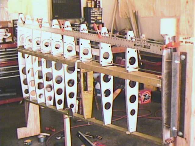
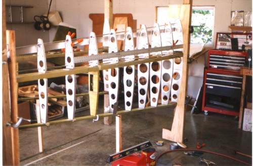
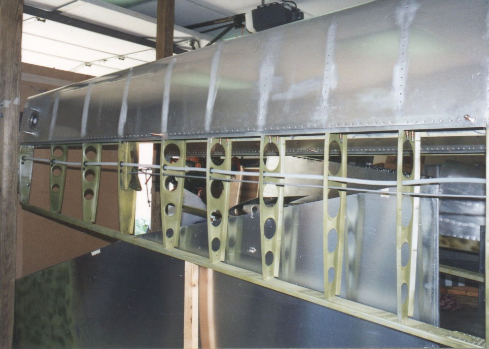
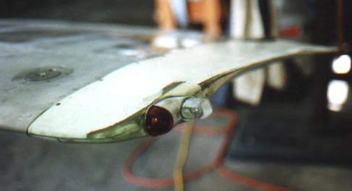
Right Wing Structure
April, 1995
(36 KB)

Wing Alignment
Wing Alignment
April, 1995
Note profile boards -
upper edges are plumb
at 90°
(58 KB)

Tip Rib Alignment
Tip Rib Alignment
April, 1995
Note profile board -
upper edge is plumb
at 90°
(42 KB)

Wing Tank Drain and Strainer
Wing Tank Drain
and Strainer

1996
(113 KB)

Wing Jig - Tip
Wing Jig - Tip
1996
(121 KB)

Wing Jig - Inboard
Wing Jig - Inboard
1996
(98 KB)

Profile boards
Profile boards
(33 KB)

Wingtip profile board
4 inches WRL to
upper edge
(30 KB)

Root rib leading edge
Root rib
leading edge

6 inches WRL to
upper edge
(36 KB)

Tip rib leading edge
Tip rib
leading edge

(29 KB)

Wing Skins
Wing Skins
March, 1996
(31 KB)

Fuel Filler
Fuel Filler
March, 1996
(19 KB)

Outer Wing Plumbing
Outer Wing Plumbing
March, 1996
(161 KB)

Riveting Wing Skins
Riveting Wing Skins
March 2, 1996
Tim said to say:
"That smile was posed"
(161 KB)

Aligning Wing Trailing Edge
Aligning Wing
Trailing Edge

(23 KB)

Learning Fiberglass 101
Learning fiberglass
from Jim Cunningham
December 27, 1995
(42 KB)

Wing tip mod
Wing tip mod
Rattray Hoerner "STOL" tip
being modified to add
nav and strobe lights
(26 KB)

Top Skin - Forward Fuselage
Top Skin -
Forward Fuselage

(25 KB)

DG to fuel tank clearance
DG to fuel tank
clearance

Note: This instrument
panel is two inches
aft of the plans.
I suggest leaving more
than 2 inches if you
use the 25 gallon tank.

(43 KB)

Side view of instruments
Side view of
instruments

(25 KB)

Forward Fuselage - Lower Channels
Forward Fuselage -
Lower Channels

(32 KB)

Baggage Compartment Floor
Baggage
Compartment Floor

(143 KB)

Elevator Bellcrank - above
Elevator Bellcrank
- above

(94 KB)

Elevator Bellcrank - rear
Elevator Bellcrank
- rear

(51 KB)

View aft into Tailcone
View aft into
Tailcone

(117 KB)

Landing Light
Landing Light
(100 KB)

Center Section Leading Edge Plumbing
Center Section
Leading Edge Plumbing

Note: Fuel line was
later relocated along bottom
(105 KB)

Tail Section
Tail section
(97 KB)

Wiring under panel - Right
Wiring under panel
- Right

(37 KB)

Wiring under panel - Center
Wiring under panel
- Center

and Main Tank outlet
(131 KB)

Wiring under panel - Left
Wiring under panel
- Left

(29 KB)

Flight Controls painted
(21 KB)

Buffing the wings
Buffing the wings
(28 KB)

Engine
Engine
(37 KB)

Plenum Chamber in cardboard
Plenum Chamber
in cardboard

Posterboard is very useful
to form templates to make
items from a single
piece of metal.
(201 KB)

Plenum Chamber complete
Plenum Chamber
complete

One spark plug access
is open
(161 KB)

Nose Cowl
Nose Cowl

from Twin Comanche
(152 KB)

Oil Cooler Door
Oil Cooler Door
Round duct is cabin
heat air inlet
(to heater muff).
(96 KB)

Cowl
Cowl
(29 KB)

Cowl open
Cowl open
(61 KB)

Oil Cooler
Oil Cooler
Note: Hard-to-see flexibile
seal between engine
baffling (moveable)
and oil cooler
(fixed to engine mount)
(64 KB)

The project history photos after June, 1997 can be found in Part Three


[ HOME PAGE ] [ CONTACT ]